
This tutorial uses the molecule we created on the previous article. It is assumed you followed it through.
Group Molecules
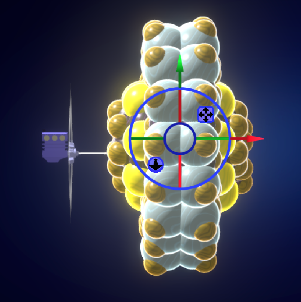
To drive a nanomachine part with a Virtual Motor, it must be a part of a group.
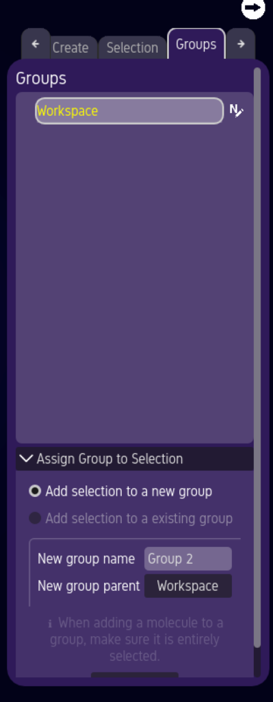
Select your molecule, then click on the “Groups” tab in the “Features Window.”

Assign your group a name by typing it into this field.
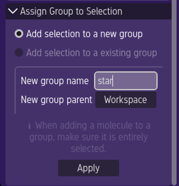
Create the Group by pressing “Apply.”
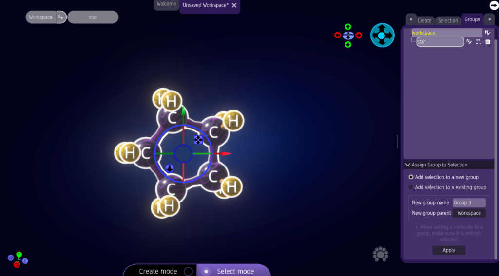
Your molecule is now contained within a group.
Attach Virtual Motors to Groups
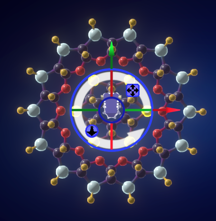
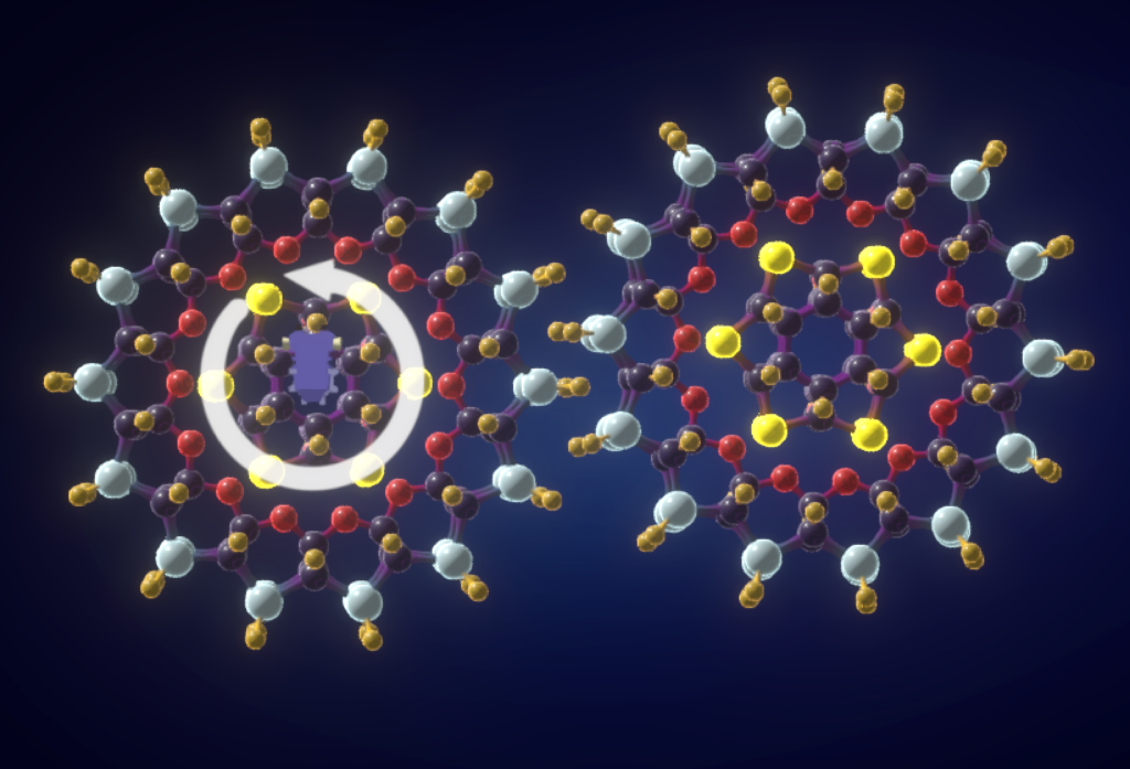
In this example, we will use a Virtual Rotary Motor to rotate this group.
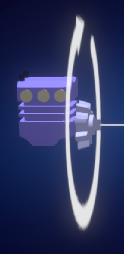
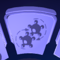
Rotary Motors spin groups around a central axis.

To create a new Virtual Rotary Motor, go to the top-level of the Action Ring, then select the Virtual Objects icon.

Click on the Rotary Motor Icon.
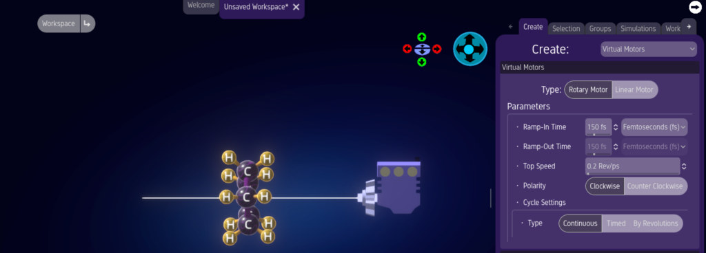
Click in the Editor Window to create your Rotary Motor.
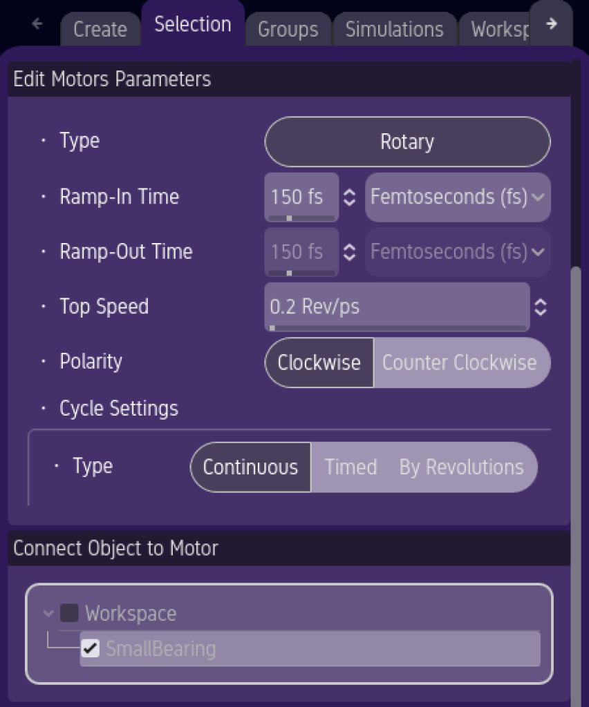
In order to make simulation time something reasonable, the default rotation speed of this motor is set to an improbably fast value.
Now, align the motor with the group you want to move.
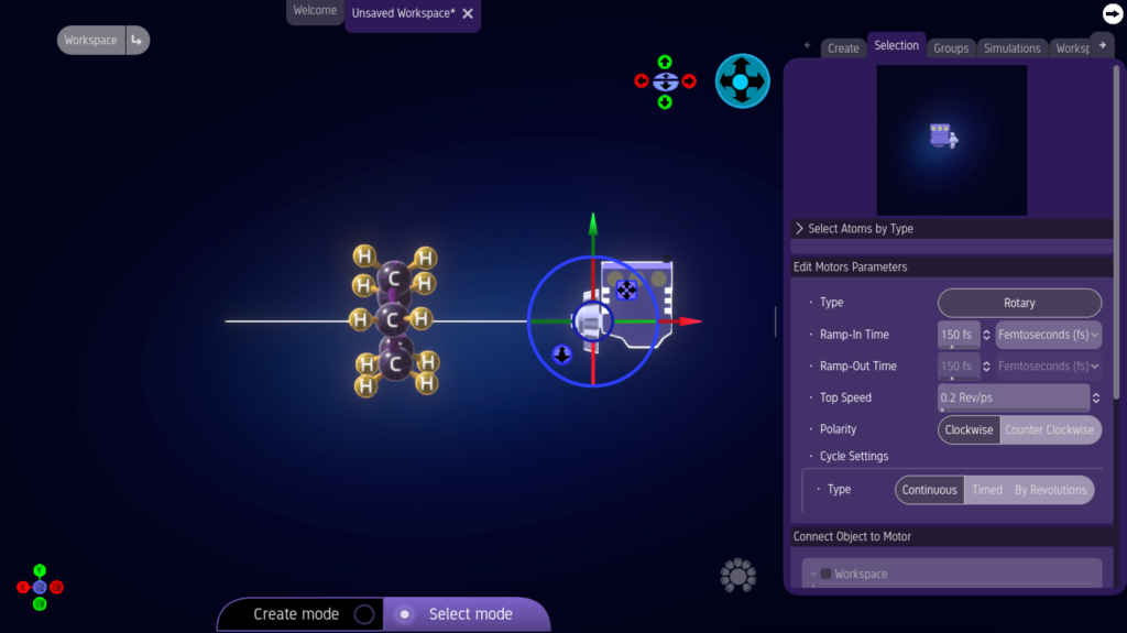
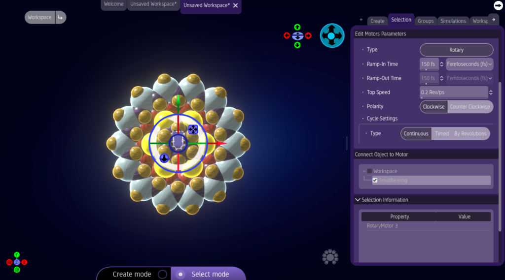
Click on the Rotary Motor to select it.
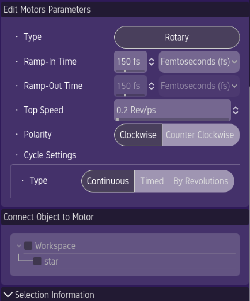
In the “Selection Tab” of the “Features Window” scroll down until you see your group’s name in the “Connect Object to Motor” panel..
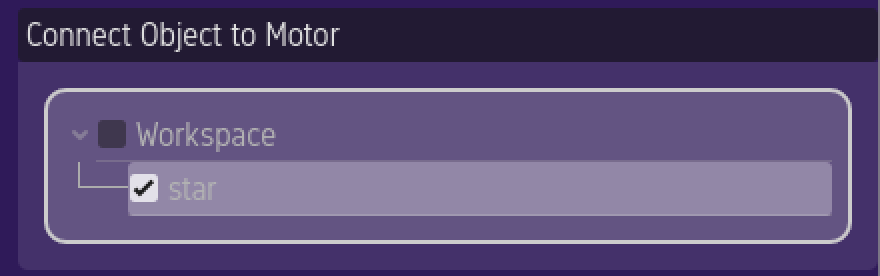
Click the box next to your group’s name to connect it to the motor.
You are now ready to try out your simple nanomachine.
Simulate Your Machine
Now that you have created a molecule, placed it in a group, and connected it to a motor, you are ready to simulate your machine.
In the “Simulations” menu of the “Action Ring” click on the “Molecular Dynamics Simulation” button.
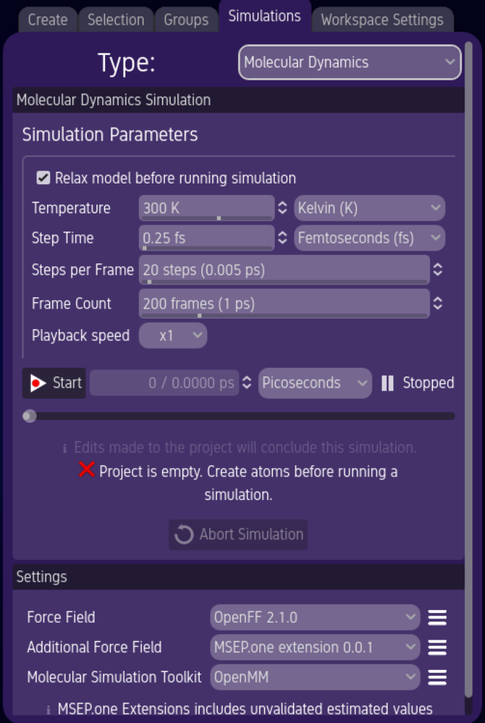
This will bring up the “Molecular Dynamics Simulation” panel in the “Features Window.”
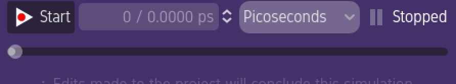
Press the “Start” button to begin your simulation.

Your simulation will begin rendering. When it has completed, you can replay the simulation using the playback controls.
Interlocking Gear Project Example
If your simulation uses multiple groups, then they may interact with each other. For example, let’s create a machine made up of 2 gears. A motor spins the first gear, which in turn spins a second gear.
Start with an empty Workspace.
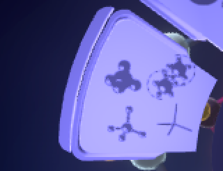
In the “File Menu” of the “Action Ring” you can click on the “Import from Library” button.
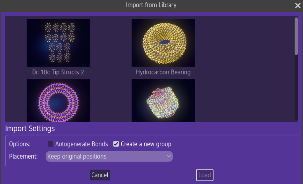
This brings up a library of existing projects.
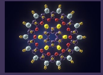
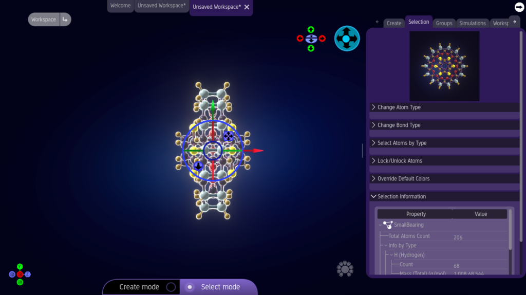
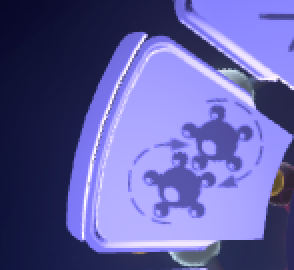
Scroll down until you see the “Small Bearing.”
Click “Load” to import it into your project.
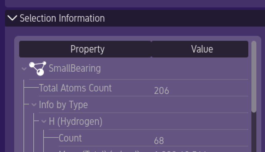
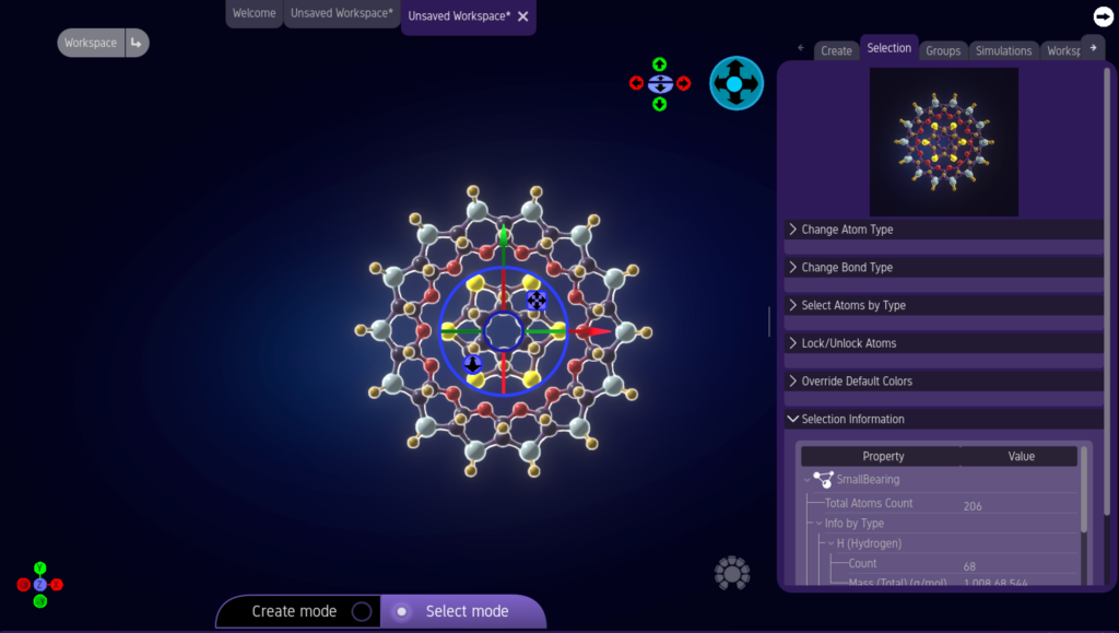
You will see that the small bearing is already in its own group called, “SmallBearing.”
The SmallBearing is actually made up of 2, disconnected rings. For this example, we are going to ignore the smaller, central ring.
You will see that the small bearing is already in its own group called, “SmallBearing.”
This will rotate your camera’s view by 90 degrees.
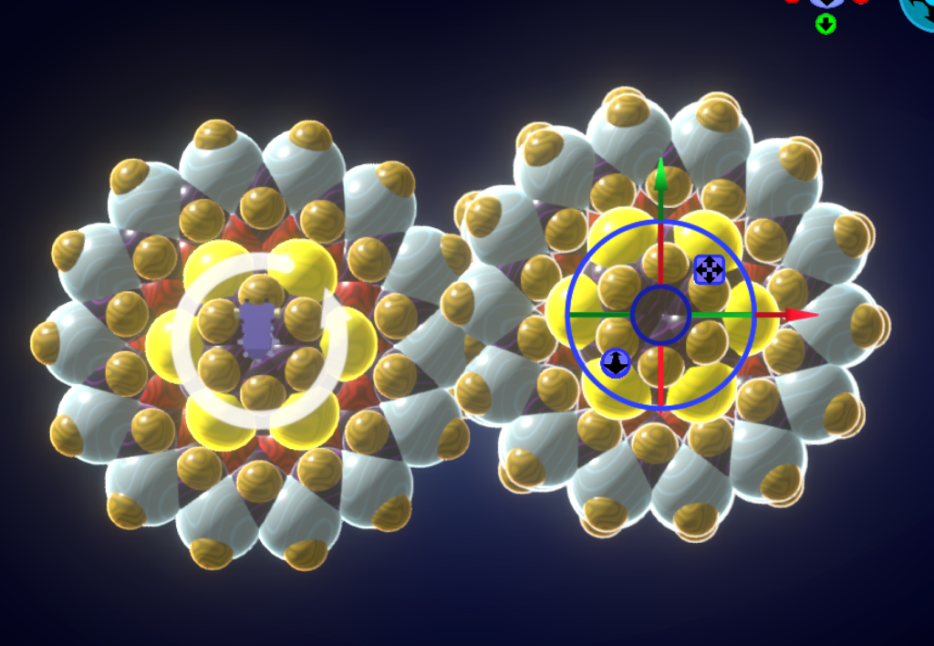
With the group selected, create a Virtual Rotary Motor. When a group is selected, creating a motor will place it at the same depth as the selected group’s center-point.

Click and drag on the central green line of the of the “Transform Gizmo” to rotate the motor’s direction until it’s drive shaft passes through the center of our “Gear.” Holding down the SHIFT key while doing this causes the rotation to jump in 15 degree increments.
Now, connect the motor to the group.
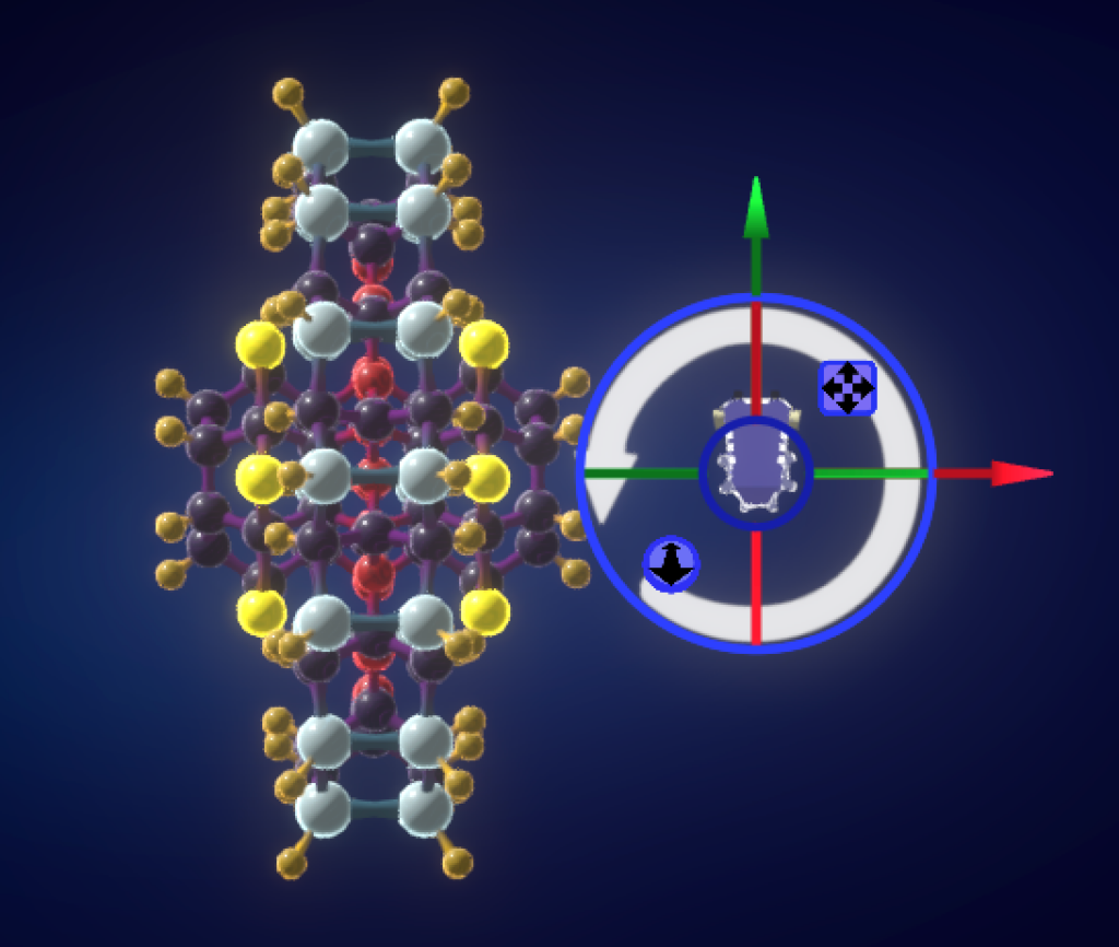
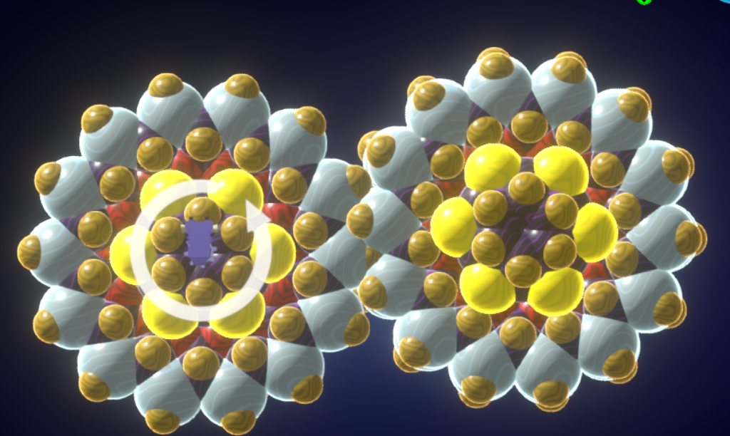
So far, you have been working in the “Balls-and-Sticks” view. Generally, this is easiest view for editing. Now, you will want to see your model in a representation the shows the distance at which atoms will interact with each other. For that, you will want to choose the “Mechanical Simulation” representation.

From the top menu of the “Action Ring” choose the “View” icon.
From within the “View” menu, click on the “Representation” icon.
Within the “Representation” menu, click on the “Mechanical Simulation” icon.
Now you are viewing your project in its “Mechanical Simulation” view. In this view, the size of each atom’s spheres spheres roughly represent the size where its electrons begin to interact with other objects.
Let’s make the 2nd gear of our machine. Select the “SmallBearing” group.
Copy and Paste the group. This can either be done from the “Edit” menu of the “Action Ring” or through the copy and paste keyboard shortcuts.
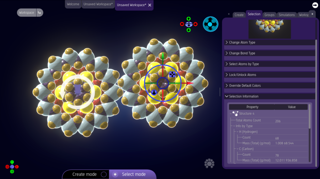
Once you have Pasted, the copy of the bearing appears selected, but on top of the original. Click-and-drag the blue “Translation Control” of the “Transform Gizmo” to move it out of the way.
If you have placed the copy correctly, it will look like the motor-driven first bearing will spin the second. But there is a problem. There is nothing holding the second bearing in place. Instead of spinning, the first bearing will simply move the second bearing out of the way.
First, make sure the 2nd bearing is meshing will with the first. Switch back to “Balls-and-Sticks” view and adjust its position.
Don’t put atoms too close together. Make them just close enough so they can interact, but if atoms are too close, the simulation will fail. You might want to briefly switch back and forth between the “Van der Waals” and “Balls-and-Sticks” representations. If the Van der Waals spheres overlap too much, you may have a problem running your simulation.
Switch back to the “Mechanical Simulation” view.
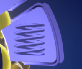
Next, you will want to hold the 2nd bearing in position, while still allowing it to spin. For this, you can use Springs and anchors.
Springs are virtual objects, representing a pulling force. Anchors represent an immovable point to which a Spring connects. The other end of a Spring must connect to an atom.
We will want to create 2 anchors on either side of and aligned with the center of the 2nd bearing.
Select the 2nd bearing by clicking on it.
Click the red X button in the camera orientation widget in the lower left of the Editor Window.
You should now be looking at the 2nd bearing edge-on.
For simplicity, we will be creating springs between our anchors and every atom in the 2nd bearing. This is not necessarily the best practice.
From the “Virtual Objects” menu of the “Action Ring”, choose the “Anchors and Springs” icon.
A spring will appear on your cursor.
Hold down the SHIFT key and the system will draw a spring between every selected atom and your cursor.

Click near the center of the 2nd bearing to create your first anchors and springs.
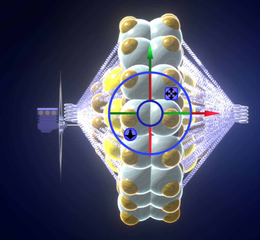
Now, do the same thing on the other side of the selected bearing.
Next, go to the “Molecular Dynamics Simulation Panel.

Turn off the “Relax Model Before Simulation” setting. Relaxing the model at this point may fully separate the molecules you need to interact with each other.
Run your simulation.
If you’ve done it correctly, the motor will drive the 1st bearing, which will in turn, drive the second.
Play with Your Own Creations
MSEP.one has many, many more features and settings to play with. Now that you have the basics down, try creating your own inventions.
As you work on your own projects, MSEP.one will probably provide feedback in the form of Warnings and Alerts. Don’t let these stress you out. If you’re new to MSEP.one don’t feel like you have to address them all. They are there to further your understanding of molecular engineering.
Have fun!